VK GameDev · Practical Blender guide
Blender for 3D Printing: Complete Beginner Workflow
Yes, you can use Blender for 3D printing. The reliable route is to model at a known size, prepare a closed mesh, check its geometry, export an STL, and inspect the sliced layers before printing.
A convincing render is not proof that a model will print. Thin surfaces, disconnected pieces, hidden internal faces, and incorrect dimensions can survive unnoticed in the viewport. This Blender 3D printing tutorial takes you through those checks, with extra guidance for sculpts, kitbashed models, and moving parts.
Start with a small, simple object. Keep its editable .blend file, and prepare a separate copy for export. You do not need paid brushes or a complex character to learn this workflow.
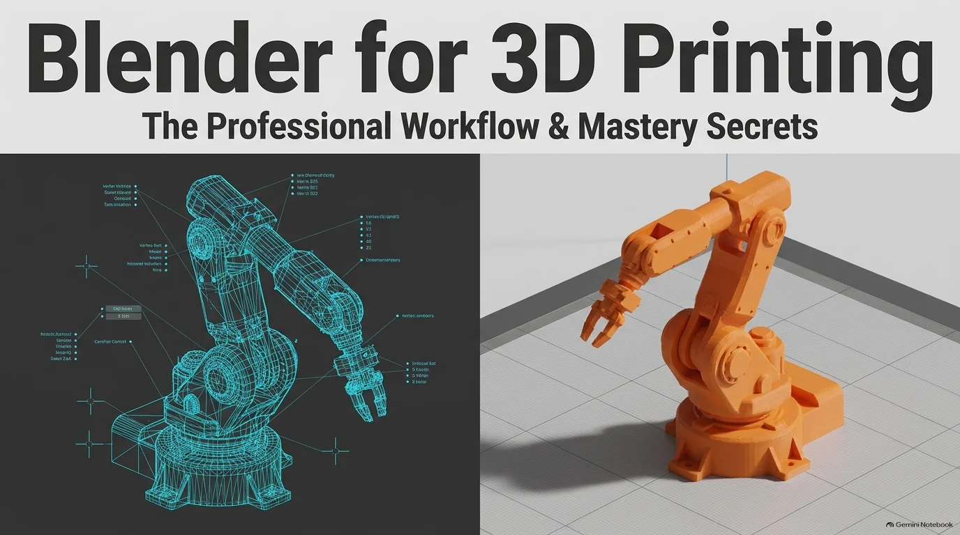
What changes when you model for 3D printing?
For a render, the final output is an image. For a print, the output is a physical object with measurable dimensions and a structure that must survive fabrication and handling. A helmet that looks solid may be only a thin surface; an arm touching a torso may not form a robust connection.
Before modeling, decide whether you are preparing for filament printing (FDM/FFF) or resin printing. For FDM, consider wall thickness, overhangs, and the direction of loading. Resin preparation also needs attention to supported islands and, when hollowing, drainage. There is no single orientation or minimum thickness that works for every machine and material. See Prusa’s design guidelines and its resin hollowing guidance.
If you are still learning to create organic forms, start with How to Learn Blender Sculpting from Scratch. This article focuses on turning that geometry into a print-ready file.
1. Set up Blender for 3D printing: units and scale
Open Scene Properties → Units. Metric with millimeters is a convenient choice, not a requirement imposed by Blender. The important distinction is between the units displayed in Blender and the numerical coordinates exported to a file.
Unit Scale controls the conversion between internal units and displayed measurements. Changing the Length display to Millimeters alone does not guarantee that an STL will arrive at the intended size. Blender documents this distinction in Scene Properties.
A consistent millimeter workflow for a new scene
- Set Unit System: Metric, Unit Scale: 0.001, and Length: Millimeters.
- Select a cube. Open the sidebar with
Nand set its X, Y, and Z Dimensions to 20 mm. - In Object Mode, use
Ctrl + A → Scale. - For this specific setup, export with Scale: 1 and Scene Unit disabled, if that option is present. This keeps one internal coordinate unit as one millimeter in the receiving slicer.
- Import the STL into the slicer. Confirm that it reads 20 × 20 × 20 mm before using the same setup for a detailed model.
This is a consistency check, not a claim that every Blender scene needs Unit Scale 0.001. A scene using Unit Scale 1 can also work with the appropriate export conversion. Do not combine settings from those two workflows. The exporter’s Scale and Scene Unit controls are explained in the Blender STL manual.
Practical habit: record your scene units and exporter settings alongside the measured slicer result. When you change Blender versions or switch slicers, repeat the small-cube check.
2. Model or kitbash parts without relying on hidden repairs
Kitbashing means assembling a model from existing pieces. Duplicate with Shift + D, then use G followed by X, Y, or Z to position the copy along one axis. Use mirroring when appropriate, and inspect the result from several directions.
Joining objects is not the same as fusing geometry
Ctrl + J combines selected mesh objects into one object. It does not automatically weld their boundaries or remove overlapping internal surfaces. A single object can still contain disconnected shells. Compare Blender’s Join operation with its Boolean modifier.
Some slicers resolve overlapping solids successfully, but you should not assume that every overlap will print correctly. For parts intended to become one continuous body, a Boolean Union is a more explicit approach. Keep the source objects separate until you have inspected the result, then validate the export copy.
Use Alt + Z to inspect overlapping geometry in X-ray mode. Look for pieces that merely touch at an edge, internal duplicates, and unintended gaps. X-ray is a visual aid—not a test proving that the mesh is watertight or free from trapped resin.
For resin prints, check the interior separately
If you hollow the model, inspect its interior with a clipping view and place drainage holes that actually connect to the cavity. Do not assume that overlapping exterior parts eliminate sealed pockets. Prusa recommends at least two drainage holes in its hollowing workflow; follow your printer and resin guidance for their dimensions and placement. Source: Prusa hollowing and drainage.
3. Apply scale where it affects the modeling result
In Object Mode, inspect the object’s Scale values. Applying scale with Ctrl + A → Scale bakes the scaling into the mesh data and resets the object’s scale to 1 without intentionally changing its visible size. This is useful before operations that depend on local dimensions. See Blender’s Apply documentation.
Do not turn this into “always apply every transform.” Applying Location is not a general requirement for STL export, and applying Rotation can affect workflows that rely on local axes. Likewise, non-unit scale does not automatically make an exported STL incorrect.
A concrete example is Solidify: non-uniform object scale can produce different thicknesses on different sides. Apply scale before setting thickness, then inspect the result. Recheck any existing modifier settings after a transform change. Source: Solidify modifier.
4. Check face orientation and give surfaces real thickness
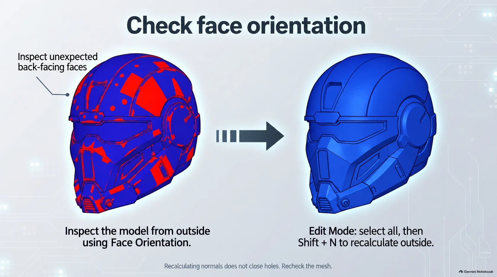
Open the Viewport Overlays popover and enable Face Orientation. With the usual overlay colors, blue indicates a front-facing surface and red a back-facing surface relative to your view. Inspect the model from outside.
- Select the mesh and enter Edit Mode.
- Press
Ato select its geometry. - Press
Shift + Nfor Recalculate Outside. - Inspect again. If the result is wrong, investigate the topology rather than repeatedly recalculating.
Red does not literally mean “a hole.” It flags face orientation; missing surfaces and ambiguous inside/outside boundaries are separate issues. Recalculation changes face direction—it does not close holes. Source: editing normals.
A printable shell also needs thickness. A single surface can look convincing in Blender while enclosing no material. Extrude it or use Solidify where appropriate, then check the inner surface and rim. Set thickness for the chosen process and inspect tight corners for intersections; do not rely on the modifier value alone.
5. Optimize a sculpt without erasing printable detail
Dense sculpts can make exporting, repairing, and slicing slower. Use a duplicate of the finished sculpt for optimization, keeping the detailed master untouched.
Add a Decimate modifier and reduce the ratio gradually. Compare the silhouette, sharp features, engraved lines, and small connections before accepting the change. Blender describes Decimate as reducing the vertex and face count while minimizing shape changes—not guaranteeing zero detail loss. Source: Decimate modifier.
If you are still sculpting on an established base mesh, our Multires modifier guide for Blender sculpting explains the subdivision-based detail stage. Keep that editable master separate from the simplified export copy.
A simple part and a detailed bust need different amounts of geometry. Judge the result at its intended print size, preserve the features that matter, and check again for mesh errors after reduction.
Make sure your sculpted detail exists in the mesh
For this STL workflow, surface detail must be represented by geometry. A material’s color, a normal map, or a lighting trick is not a substitute for a raised scale or carved groove. Keep details broad enough to survive both mesh simplification and the selected print process.
Choose surface details for the object's final size: broad folds, visible cracks, and readable scars can matter more than tiny pores on a small miniature. Finish the geometry, then repeat the mesh and slicer checks after detailing.
Optional tools · VK GameDev products
Sculpt the detail faster: two brush packs for this workflow
You can complete this beginner workflow with Blender's standard tools. When you want a reusable library of surface details, these two packs serve different needs: a broad collection for mixed projects, or a focused skin library for character work.
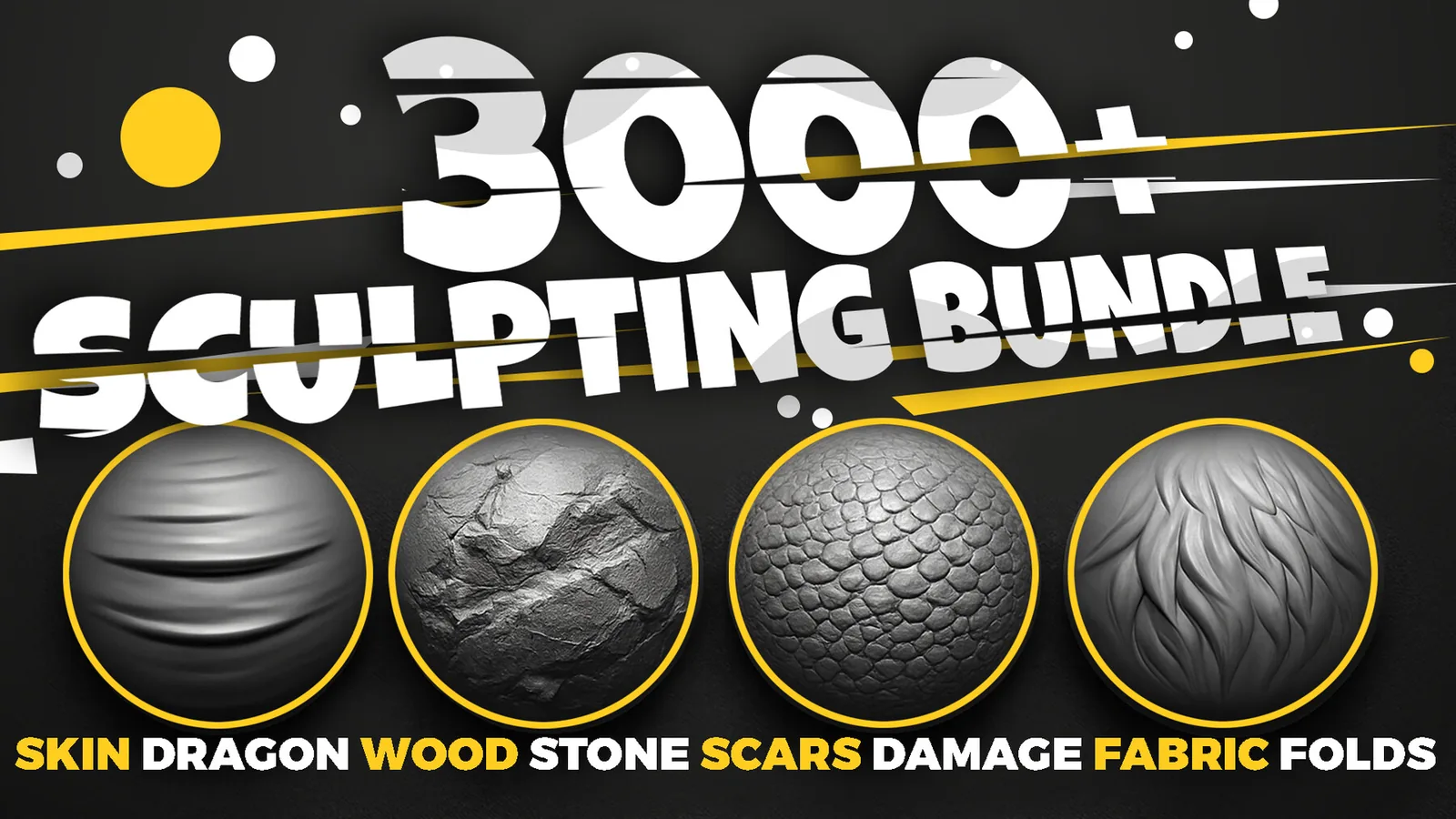
3000+ Blender Sculpting Brushes Bundle
For miniatures, props and scenic bases. Explore skin, fabric, rock, wood, damage and ornament brush families in one library. Use the categories that match the model—for example, rock cracks on a base or folds on a character's clothing.
Choose it when a project mixes several surface types.
Explore 3000+ Blender sculpting brushes →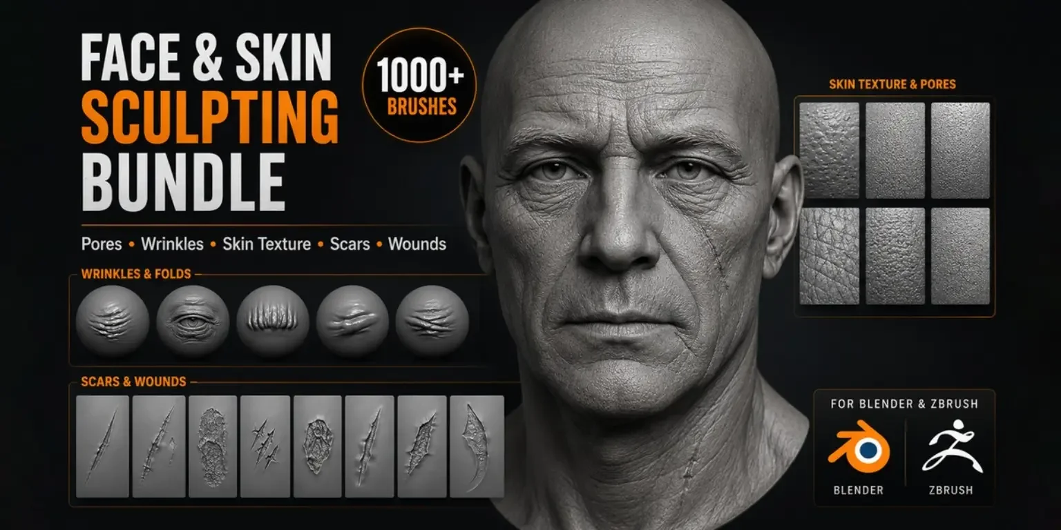
1100+ Face & Skin Sculpting Brushes Bundle
For character busts and skin-detail work. Six packs cover pores, wrinkles, lips, hands, wounds and scars. Select details that remain readable at your chosen print scale instead of adding microdetail that the printer cannot resolve.
Choose it when human skin and character damage are the focus.
Explore the Face & Skin Bundle →
Watch the Face Skin brushes demonstration
Product demonstration linked from the Face & Skin Bundle page. It demonstrates digital sculpting, not a physical print test.
6. Use the Blender 3D Print Toolbox to find mesh problems
The 3D Print Toolbox extension provides geometry checks, volume and surface-area analysis, and Make Manifold cleanup. Installation instructions differ between Blender versions: newer versions use the Extensions workflow, while older tutorials show a bundled add-on. Use the extension listing for the version you install.
Select the export copy and open the 3D-Print panel in the viewport sidebar. Run Check All, then inspect the reported selections. Check the same final geometry you intend to export, including the result of relevant modifiers. Source: 3D Print Toolbox reference.
A non-manifold edge can be a boundary edge at a hole, an edge shared by too many faces, or loose geometry. It is not simply another word for a visible hole. Thickness and intersection warnings also need interpretation in the context of the intended solid.
Repair the cause, not just the warning count
- Save a backup before automatic cleanup.
- Try Make Manifold when appropriate, then compare the repaired result with the original.
- For manual repairs, isolate the reported region. Remove only confirmed unwanted geometry.
- Close an unintended simple boundary with a suitable fill; preserve intentional openings and wall thickness.
- Recheck normals, dimensions, and the mesh report.
Do not delete every highlighted edge and press F indiscriminately. A complex opening may need reconstructed topology, and a careless fill can close an intended opening or create a self-intersecting face.
7. Export STL from Blender for 3D printing
Keep the editable source, select only the finished print geometry, and use File → Export → STL. Review these options:
- Selection Only: include the intended objects, not spare meshes or construction geometry.
- Scale and Scene Unit: use the combination verified with your small-cube test.
- Apply Modifiers: include the evaluated modifier result when that is the geometry you intend to print.
- Forward and Up axes: match the receiving workflow and inspect the imported result.
These controls are documented in the Blender STL reference. Menu labels may differ in newer releases. A camera or light is not exported as a printable camera or lamp: the practical concern is unintended exportable geometry.
Choose orientation for the actual printing process. A model that looks upright on screen may not have the best print orientation, and a resin model may need a different setup from its FDM counterpart.
8. Slice the model and inspect the actual layers
Import the STL into a slicer that supports your printer, such as PrusaSlicer. Select the correct printer and material profiles. Confirm dimensions, orient the model, configure supports where needed, and generate the sliced preview.
Move through the layers, particularly where one part joins another or a thin feature first appears. Look for missing walls, disconnected regions, unexpected internal surfaces, and supports touching important details. For resin, also inspect the hollowed interior and drainage routes. A normal-looking whole-model preview is not enough.
| Problem | What to check first |
|---|---|
| Model imports much too small or large | Scene units, export conversion, and imported dimensions. Repeat the 20 mm cube check. |
| A feature disappears in the layers | Its actual thickness, the mesh boundary, and the selected slicing profile. |
| Artifacts appear where parts overlap | Unresolved shells, duplicate or coplanar faces, and the Boolean result. |
| Printed surface looks faceted | Actual mesh resolution and any detail removed during simplification. |
| A hollow resin part has a sealed pocket | Interior connectivity and drainage-hole placement. |
Fix Boolean artifacts at their source
If artifacts appear where parts intersect, inspect the Boolean operands and resulting mesh for duplicate faces, coincident surfaces, and unintended internal boundaries. Correct the geometry on a backup copy, recheck dimensions, and slice again. Reference: Boolean operations.
Once the preview is sound, save the slicer project and export the machine-compatible print file. Complete your printer’s normal setup checks, then make a small test print. Treat that print as feedback: measure it and inspect connections before committing to a large or time-consuming version.
9. Design clearances for parts that must fit or move
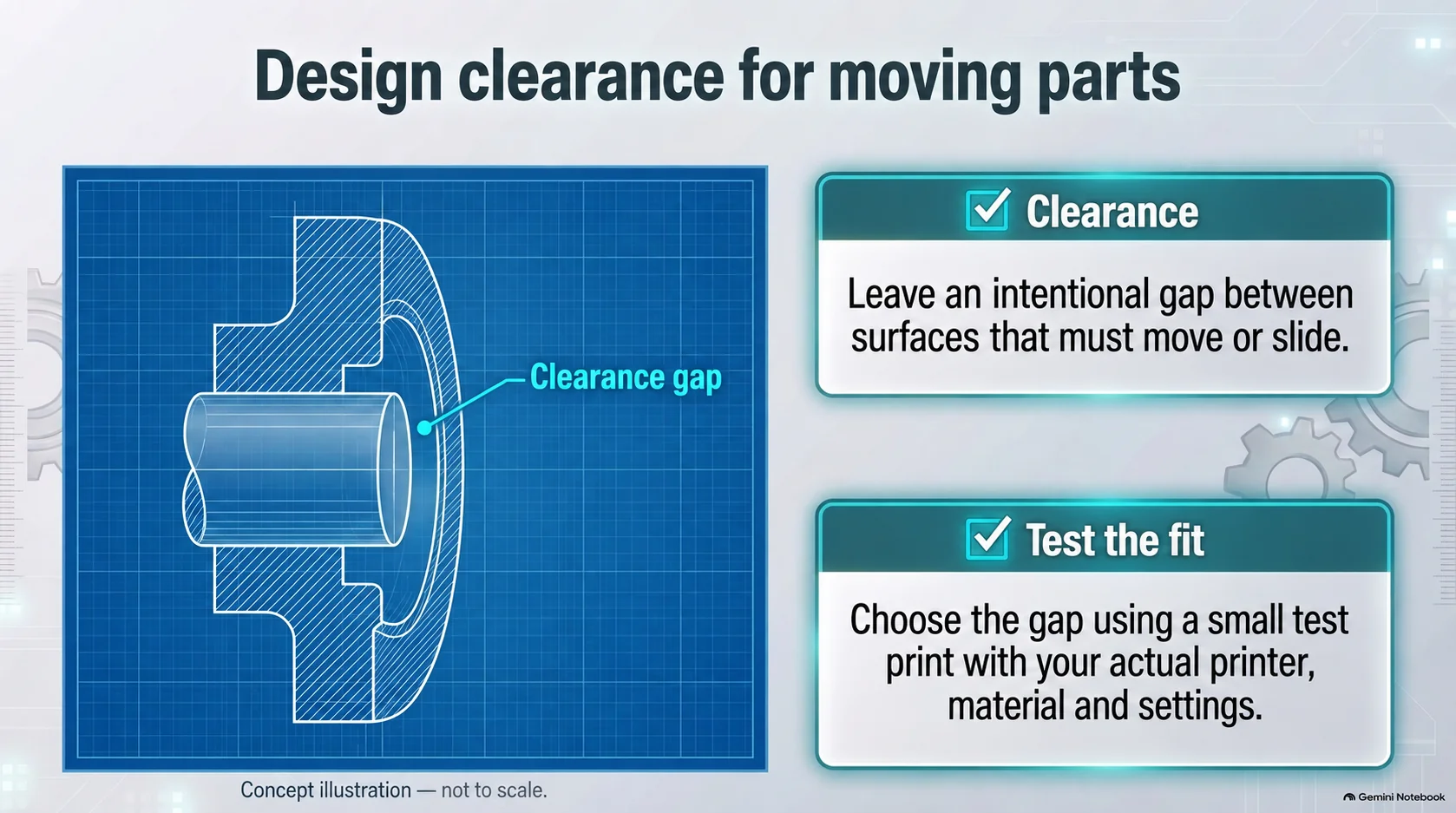
Clearance is the intentional gap between mating surfaces. Tolerance describes acceptable dimensional variation. In practice, the clearance you model must account for what the printer and material can reproduce.
A nominal 5 mm pin and a nominal 5 mm hole leave no designed gap. For a sliding fit or a print-in-place mechanism, that is a risky starting point. Use a small fit test with several candidate clearances, then select the result that works with the actual material, orientation, and settings.
There is no universal clearance value. State whether a gap is measured per side or across the diameter: a 5.0 mm pin inside a 5.4 mm hole has 0.4 mm diametral clearance, or 0.2 mm per side when centered. Prusa discusses the variables that affect fit.
Blender 3D printing checklist: before you press Print
- The slicer reports the intended dimensions.
- The exported geometry matches the evaluated Blender model.
- Unintended boundaries, internal faces, and overlaps have been addressed.
- Face directions are consistent with the intended solid.
- Walls and small connections suit the selected process.
- Decimation has preserved necessary shape and detail.
- Only the intended geometry is included in the STL.
- Orientation and support placement have been reviewed.
- Moving parts have a deliberate, tested clearance.
- Hollow resin models have accessible drainage routes.
- The sliced layers have been inspected, not just the unsliced model.
- The editable source and slicer project have been saved.
Related Blender 3D printing videos
These videos are optional visual companions. For current settings and the qualifications explained in this guide, use the official documentation linked in each section; older tutorials may show a different Blender interface.
- 3D Print Toolbox Workflow with Slicer — the full-workflow companion.
- Blender Model to 3D Print — Quick Guide — a short overview.
- Reduce Triangles, Make Manifold, Export a Clean STL — optimization and export topic.
Frequently asked questions
Is Blender good for 3D printing?
Blender can create and prepare printable meshes. It is particularly useful when your work already involves sculpting or mesh modeling. Successful printing still depends on dimensions, solid geometry, the selected manufacturing process, and slicer checks—not the modeling software alone.
Can Blender make STL files?
Yes. Blender provides an STL exporter. Select your print-ready geometry, review the export options, and confirm the imported dimensions in the slicer. Keep the .blend file for future edits.
Do I need a Blender 3D printing add-on?
You do not need the 3D Print Toolbox just to export STL. It is useful for identifying geometry problems and inspecting volume, area, and potential print issues before exporting.
Does Ctrl + J make a model watertight?
No. Join creates one object from the selected objects; it is not a Boolean Union or a mesh-repair operation. Validate the intended solid separately.
How much mesh detail should I keep?
Preserve the geometry needed for the intended print size and detail. Reduce unnecessary complexity while checking the silhouette and important features; a fixed polygon count is not a print-quality standard.
Can I print my Blender materials and normal maps?
Not through this STL workflow. For physical relief, convert the intended detail into mesh geometry. Color printing requires a compatible file format, printer, and preparation workflow of its own.
Can I skip the slicer check if the mesh is manifold?
No. A manifold mesh can still be too thin, poorly supported, incorrectly scaled, or unsuitable for the chosen process. Inspect the layers and make a test print when fit or fine detail matters.